
Tunnel Ventilation and its Influence on Fire Behaviour:
INTRODUCTION
INTRODUCTION
.jpg)
The majority of road tunnels of significant length have some form of ventilation system for various reasons including smoke control in a fire emergency. These fall broadly into two categories, transverse systems and longitudinal systems, although an increasing number of tunnels, for example the refurbished Mont Blanc tunnel [1], have elements of both types installed. Transverse ventilation systems use air ducts, generally either above a false ceiling within the tunnel or below the road deck, to supply and extract air at periodic locations along the length of the tunnel. Sometimes, while the supply duct may extend along the entire length of the tunnel, extraction is only carried out at a small number of locations, such systems are known as semi-transverse systems. Longitudinal systems use jet fans, generally mounted on the ceiling, to move air along the main tunnel void.
In the event of a fire the primary function of any ventilation system is to maintain a smoke free egress path for escaping tunnel users and to allow smoke free access to the fire location for the fire brigade. In fully transverse systems, the strategy is generally to provide maximum extraction in the vicinity of the fire, while air supplies are generally reduced. In semi-transverse systems, the strategy is often to provide maximum extraction on one side of the fire, to allow safe egress on the other side. While the strategy used with longitudinal systems is to blow all the smoke to one side of the fire, once again allowing safe egress on the upwind side.
However, any movement of air in the vicinity of the fire will have an impact on the fire development, smoke production, peak fire size and propensity for fire spread to other vehicles. This article reviews research onto these aspects of the interaction between ventilation systems and fire behavior.
FIRE vs. VENTILATION
Critical Ventilation Velocity:
The single most well investigated tunnel fire phenomenon is critical ventilation velocity (CVV). This relates to tunnels with longitudinal flow, including all longitudinally ventilated tunnels and many (semi-) transversely ventilated ones. Various experimental, theoretical and computer modelling studies have been carried out, from Thomas in the 1950 and 1960's to ongoing work carried out by Wu with various co-investigators. While approaches vary, it is commonly found that in ‘typical’ tunnel environments, with fires of significant size, the CVV falls somewhere between 2.5 and 3 m/s. There is generally found to be a relationship between CVV and fire size, although some studies suggest that there is a ‘super critical ventilation velocity’ which is sufficient to control the smoke from a fire of any size.
One factor that is masked by this focus on ventilation velocities rather than ventilation systems is the ‘throttling’ influence of a fire in a tunnel, characterized experimentally by Lee et al. in the 1970's and more recently described numerically by Colella et al. Essentially, in order to generate a given airflow velocity in a tunnel, more thrust from the fans is required for a larger fire compared to a smaller fire. Thus, while the CVV for, say, a 30 MW fire may be the same as that for a 60 MW fire, in practice the number of jet fans required to generate the critical flow for the larger fire would be greater.
Many tunnel fire safety strategies circumvent this issue by simply utilizing maximum ventilation in any emergency fire situation. However, this may have adverse effects on the fire itself and may not be the best strategy.
Ventilation Velocity vs. Fire Size:
It has previously been demonstrated that there is a relationship between the heat release rate (HRR) of a fire and longitudinal ventilation velocity in a tunnel. This has been observed to vary both with tunnel size and fuel load.
While there tends to be a small influence on heat release rate with applied ventilation for pool fires (small pool fires tend to be reduced in HRR with applied velocity, larger pool fires may be increased by up to 50%), there is a much larger enhancing influence of ventilation on vehicle fires, especially heavy goods vehicle (HGV) fires, and particularly in smaller tunnels, see Figure 1. In Figure 1 (and other publications) the HRR enhancement due to ventilation is described in terms of a factor k, defined as k = Qvent / Qnat, where Qvent is the peak HRR of a fire in a tunnel with a given longitudinal ventilation velocity and Qnat is the HRR of a similar fire in a similar tunnel subject to natural ventilation conditions. Thus, for a HGV fire in a two lane tunnel with a longitudinal ventilation rate of 4 m/s, the peak HRR would be expected to be slightly over twice that of a similar fire in naturally ventilated conditions.
 |
| Figure 1 – The enhancing influence of longitudinal ventilation velocity on HGV fires in single and two lane tunnels. The enhancement is described in terms of the factor ‘k’. (Note the logarithmic scale on the vertical axis; these graphs are representations of the ‘expectation’ values from a probabilistic study, in practice there will be a distribution of k values for each velocity). |
Smoke production is directly proportional to HRR. As the general trend appears to be that higher airflow rates result in higher peak HRRs, it would seem sensible, in general, to endeavour to keep ventilation velocity low during tunnel fire incidents, in an attempt to keep the fire severity and smoke production as low as possible.
Ventilation Velocity vs. Fire Spread:
A study was carried out in 2003-04 investigating (amongst other things) the influence of longitudinal ventilation velocity on fire spread by flame impingement from an initial fire to a HGV ‘target’ positioned some metres downstream of it. In general it was found that, for a fire of given size, the probability of fire spread by flame impingement to the target object was likely to increase with increasing ventilation velocity, see Figure 2. Thus, once again, it would seem sensible to keep ventilation velocity low during tunnel fire incidents, to reduce the risk of fire spread to downstream vehicles.
 |
Figure 2 – Variation of probability of fire spread from an initial fire to a ‘target’ HGV, positioned 5m downstream, with longitudinal ventilation velocity, in a two lane tunnel.
Other studies have investigated fire spread by remote ignition. This also varies with ventilation velocity, but it is generally found that the critical HRR for fire spread by remote ignition increases with increasing ventilation velocity. Hence, the likelihood of spread (of a fire of unknown size) decreases with increasing ventilation velocity.
This study considered the combined effects of ventilation on increasing HRR, increasing the critical HRR for fire spread by remote ignition and increasing the likelihood of fire spread by flame impingement to an adjacent HGV ‘target’. It was found that fire spread by remote ignition is only likely at very low airflow velocities, while at higher velocities the chance of fire spread by flame impingement dominates. It was observed that for a HGV fire in a typical two lane tunnel, the overall probability of fire spreading to the target HGV (by either spread mechanism) was lower when the ventilation velocity was about 2 m/s than all other considered ventilation velocities, see Figure 3.
 Ventilation Velocity vs. Fire Growth:
It was recently observed that there is also a relationship between longitudinal ventilation velocity and the rate of fire growth in the initial stages of a fire. It was observed that the initial fire growth of a ‘HGV cargo’ type fire in a tunnel may be split into two distinct stages: (i) the ‘incipient’ or ‘delay’ phase, during which the fire remains relatively small, often for several minutes, followed by (ii) the growth phase, where the fire grows rapidly, generally in an approximately linear manner with regard to time.
It was observed that longitudinal ventilation velocity has an influence over the duration of the incipient phase; ventilation rates of about 2.5 – 3 m/s generally result in shorter duration's than higher and lower ventilation rates, see Figure 4 (a). It was also observed that the rate of growth in the growth phase is also influenced by longitudinal ventilation flow; ventilation rates of about 2.5 – 3 m/s appear to result in much faster growth rates than higher or lower ventilation velocities, see Figure 4 (b).
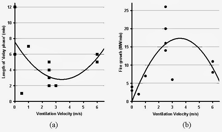
Thus, in order to maximize the duration of the incipient phase and to minimize the rate of growth in the growth phase, ventilation rates in the locality of 2.5 to 3 m/s should be avoided.
These observations are made on the basis of fire tests carried out in the Runehamar tunnel in 2003, the 2nd Benelux tunnel in 2001 and the Hammerfest tunnel in 1992. It is acknowledged that these observations are based on a very limited sample of fire tests and further research is required to confirm or refute the observed trends.
Transverse Ventilation Systems:
Very little research has been carried out with specific regard to the influence of transverse ventilation on fire behavior in tunnels. Certainly, any semi-transverse system which produces a longitudinal flow past the fire location will result in the same responses as a flow generated by a longitudinal ventilation system. Beyond that, the main concern with transverse systems is whether they are actually capable of extracting the volume of smoke produced by a fire in a tunnel. Many older transverse systems were designed on the basis of a design fire between 20 and 50 MW in size, yet research and experience in the past decade has shown that real vehicle fires may be many times larger than this and so existing transverse ventilation systems may simply not be able to handle real large fires.
Summary
So, on the basis of the reviewed research on fire behaviour in tunnels, the following observations may be made:
A good compromise:
The refurbished system in the Mont Blanc Tunnel utilities aspects of both fully-transverse (with dampers on the extract points) and longitudinal systems. In a fire emergency, the extraction system is configured such that it will provide extraction only at the dampers on either side of the fire location, while the jet fans will drive fresh air towards the fire location from both sides. This should, in principal, result in maximum smoke extraction on either side of the fire yet generate negligible longitudinal flow at the fire location (minimizing growth, peak fire size and fire spread). Thus, the smoke logged zone is kept relatively short, and smoke free egress paths on both sides of the fire should be maintained.
Systems such as this one rely on detection systems being able to identify the location of a fire with a high degree of accuracy, and also require careful monitoring and control of the longitudinal flow in the tunnel. The systems in the Mont Blanc tunnel have been demonstrated to work well in test scenarios, but have yet to demonstrate their utility in a real fire incident.
CONCLUDING COMMENTS:
For years there has been a focus on two aspects of tunnel fire behavior CVV for smoke control and peak HRR as a measure of fire severity. The transport tunnel industry seems to be shifting to a new position where sprinklers and WMS are being used for fire protection. In this new paradigm, peak HRR should not be our concern anymore – if a fire reaches its natural peak HRR, then the suppression system has failed in its task!
Rather, the focus of attention must shift towards the early stages of fire development – the growth phase. When the fire is small, the smoke production rate is small and, hence, the CVV remains small. Based on the observations above, the best way to keep the fire small in its initial stages is to either keep the ventilation velocity low (at about 1 m/s) or take it up to high velocity (greater than 5 m/s).
It is also desirable to activate the suppression system as early as possible, so it is important to invest in and develop good fire detection systems. If suppression is activated early there is good hope that the fire will not spread, there will not be much smoke production and the fire may be suppressed quickly. Based on the current knowledge of WMS, it is not known if these are effective at high ventilation velocities so, until further research is carried out, a low velocity condition would generally be preferred.
Ventilation, suppression and detection systems should not be considered to be separate entities, but three parts of an integrated fire safety system.
ACKNOWLEDGEMENTS:
This article is based on part of the paper “Ventilation and suppression systems in road tunnels: Some issues regarding their appropriate use in a fire emergency” by Ricky Carvel, Guillermo Rein & José L. Torero, presented at the 2nd International Tunnel Safety Forum, Lyon, France, April 2009.
This article has summarised the results of several projects, several of which were funded by EPSRC – their funding is gratefully acknowledged. Thanks also to Dr Alan Beard and Prof. Paul Jowitt at Heriot Watt University, to the tunnels team at Jacobs (UK) Ltd. and to Le Crossing Company Ltd.
|


